MiniMig198itx
Minimig 1.98 ITX motherboard, rendered from native CAD on a dark studio floor

PRECISION ARRAYS / THE MINIMIG 198ITX PROJECT

A classic heart.
A new dimension.

Classic computing.
Reimagined in hardware.

A Spartan-3 FPGA, six SRAM devices and a physical MC68000. Meet the 170 mm motherboard that brings the original Minimig spirit into a new perspective.

FPGA / 68000 / RETRO COMPUTINGDevelopment hardware
01 — THE IDEAScroll to discover ↓Native CAD · Blender studio render
XC3S400Xilinx Spartan-3 FPGA
6 MiBSix asynchronous SRAM devices
170 × 170Board footprint · millimetres
06Copper layers

02 / HARDWARE EXPLORER

Turn it around.
Take it apart.

Explore the current native KiCad board, turn it over, or separate the connector and component groups to reveal the PCB beneath.

MINIMIG 198ITX / NATIVE BOARDThe heart of the project.170 × 170 mm PCB · six copper layers
Preparing the hardwareLoading native CAD geometry…
Native KiCad geometry
Drag to orbit · Scroll / pinch to zoom · Right-drag to pan
Native 198itx PCB, including six SRAM devices and the translated MC68000 interface.Geometry exported from the saved design

The board Current native components, connectors and silkscreen.

Exploded view Separate component groups to see the board beneath.

Both faces Inspect the underside, pads and printed markings.

03 / THE ARCHITECTURE

Classic by design.
Connected by purpose.

Follow the design from programmable logic and memory to picture, sound and the connections around the board.

MINIMIG 198ITX / FUNCTIONAL DESIGNPROGRAMMABLE CORE
Functional paths · selected interfaces shown

The Spartan-3 FPGA connects to six SRAM devices, the translated MC68000 bus and the AT91SAM7S256 controller.

FOLLOW THE DESIGN

Classic roots. Programmable heart.

The Spartan-3 FPGA connects to six SRAM devices and a physical MC68000, with an ARM controller handling configuration.

FPGA cores and firmware determine the behaviour of the system.

A classic foundation.
Distinct roles, working together.

Explore a functional view of the design, then return to the native model to see the components themselves.

BENEATH THE COMPONENTS

Six layers.
A foundation for every signal.

Signal routing, power and ground share a defined six-layer stack. In1.Cu and In3.Cu are ground reference layers. F.Cu, In2.Cu and In4.Cu carry signals and power; B.Cu is named GND but also carries signal routing.

Signals Ground Signals / power
Open the native stackup drawing ↗
PCB CROSS-SECTIONTOP ↓ BOTTOM
  1. 01F.CuSignals / power
  2. 02In1.CuGround
  3. 03In2.CuSignals / power
  4. 04In3.CuGround
  5. 05In4.CuSignals / power
  6. 06B.CuGround / underside components
Dielectric separates the copper layers · thickness exaggerated

04 / THE BOARD DESIGN

A classic heart.
A board built around it.

A physical CPU interface and programmable logic share one motherboard. Follow the design from the 68000 bus to the connections that make it a complete system.

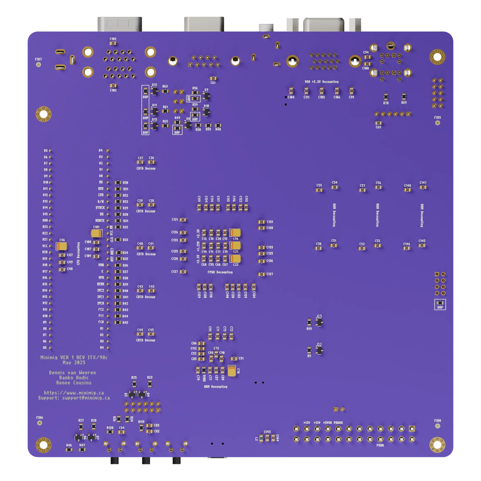
Minimig v1.98 ITX board, top view showing components, connections and silkscreen198ITX / NATIVE BOARD

PHYSICAL 68000 · PROGRAMMABLE LOGIC

The original connection.

A physical 64-pin MC68000 connects to the Spartan-3 through five bus-translator devices. A 16-bit data bus, A1–A23 address lines and processor control signals bring the original architecture into the programmable design.

Processor
MC68000 · DIP64 package
Signal connections
49 translated signal channels
Memory
6 × 1 MiB asynchronous SRAM
Open the top assembly drawing ↗
Minimig v1.98 ITX board, underside view showing components, connections and silkscreen170 MM / SIX LAYERS

170 MM FOOTPRINT · CLASSIC CONNECTIONS

Every side has a purpose.

PS/2, DB9 controllers, RGB video and serial preserve the connections of classic computing. microSD, Mini-USB service, an ATX supply connection and front-panel controls complete the board’s hardware interfaces.

PCB outline
170 × 170 mm
Mounting
Four 3.2 mm holes
Construction
Six copper layers
Open the bottom assembly drawing ↗
SIX SRAM DEVICES · ONE SHARED BUS

Shared signals. Individual selection.

Six 1 MiB SRAM devices share a 16-bit data bus and address lines. Each device has its own chip select, giving the FPGA access to 6 MiB of physical memory.

CONNECTIONS ACROSS GENERATIONS

From joystick to serial.

Explore all 17 connection groups in the port map, then turn the native model to see their physical positions.

Explore every connection ↗

Minimig 198itx development hardware. The interactive model follows the saved PCB; its exploded view separates component groups for inspection. Firmware and loaded cores determine operating modes and memory mapping.

05 / THE ASSEMBLY BOOK

Good design.
Down to the details.

Five A4 drawings cover top and bottom assembly, stackup, routing and power. Print at 100% for the 1:2 assembly reference plans.

Open the 5-page board guide ↗

SELECT A DRAWING

A4 landscape drawings
Updated 17 October 2026

01 / 05

Board / top assembly

06 / WHERE WE ARE

Real hardware.
A continuing story.

CURRENT BOARD SNAPSHOT

Minimig / 198itx

The native design brings together a Spartan-3, a physical MC68000 and 6 MiB of SRAM. The model comes directly from the saved KiCad PCB, including components and silkscreen on both faces.

198itx / 98c board geometry · native components throughout.
DOCUMENTED DESIGN

Five sheets. Every detail.

Top and bottom assembly, the six-layer stackup, routing, power and buses. The board guide follows the hierarchical circuit sheets at the end of the KiCad schematic set.

Assembly documentation is included in the schematic project.
NEXT CHAPTER

Build. Test. Refine.

Bring-up, core and firmware integration, memory mapping and peripheral testing. The native hardware provides the foundation for continued system development.

Hardware and firmware validation continue together.
Minimig / 198itx

A classic heart. A new dimension.

Explore the hardware ↑

BUILD / ASSEMBLE / EXPLORE

The files.
Build and explore.

Production files, software and interactive documentation for Minimig v1.98.

Read the engineering guide ↗
Minimig v1.98 downloads
TypeFileWhat it contains
ProductionGerbers, drills and assembly filesAll copper layers, mask, paste, silkscreen, outline, drill maps, component BOM and placement CSV.
SchematicsComplete schematic PDF33 A4 sheets with consolidated circuits, clear labels and five refreshed board drawings.
DocumentationOffline engineering guideUpdated 17 October 2026: HTML guide, interactive BOM, A4 drawings, PDFs and 17 preservation checks.
BOMComponent list (CSV)Component references, values and footprint information from the matching project.
ChecksumsSHA-256 checksumsVerify the downloaded release packages.
ARM + FPGAS6 core + MM2609S5 ARM firmwareThe matched release: redesigned OSD, 20/30/40/50/60 MHz CPU selection, Amiga quadrature mouse and improved timing. Includes SD-card and SAM-BA images with installation notes.
Software sourceS6 FPGA and ARM source + timing reportsMatching RTL, ARM firmware code, build scripts, tests and timing evidence. Documentation is included as plain text.
Release guideInstall the release and choose a CPU clockVersion checks, installation steps, CPU profiles and native Amiga mouse support.
Assembly drawingOpen PDF ↗
Enlarged assembly drawing

Use the PDF for vector detail and printing.