






 TOP / NATIVE BOARD
COMPONENTS · CONNECTIONS
The hardware, in view.
The FPGA, memory and peripheral connections, seen directly from above.
Open the top assembly drawing ↗

PRECISION ARRAYS / THE SIDI-128 PROJECT
Reconfigurable hardware.
Connections across generations.
A Cyclone 10 FPGA, 128 MB of SDRAM, and a rich mix of classic and current interfaces. Meet the board at the heart of SiDi-128.
02 / HARDWARE EXPLORER
Explore the native KiCad board and separate its component groups. Switch to printed R18 or FR4-R7 to lift the lid and reveal the enclosure assembly.
Interactive 3D is unavailable. Explore the native renders and assembly drawings below.
View assembly guide ↓The board Inspect the native board, or separate its component groups.
Printed R18 Four removable faceplates and an eight-screw lid.
FR4-R7 Six panels, metal posts and countersunk fasteners.
THE WORLDS INSIDE
03 / THE ARCHITECTURE
Follow the design from programmable logic and memory to picture, sound and the connections around the board.
The Cyclone 10 FPGA connects to two SDRAM devices, dedicated clocks and the ATSAMV71 controller.
FOLLOW THE DESIGN
The Cyclone 10 LP FPGA connects to two SDRAM devices, with dedicated clocks and an ATSAMV71 controller.
FPGA cores and firmware determine the behaviour of the system.
Explore a functional view of the design, then return to the native model to see the components themselves.
BENEATH THE COMPONENTS
Signal routing, ground references and power share a carefully defined stack. Three internal ground layers provide reference planes within the board.
04 / THE BOARD DESIGN
Look closer at the components, connections and underside of SiDi128 before exploring its enclosures.
TOP / NATIVE BOARDCOMPONENTS · CONNECTIONS
The FPGA, memory and peripheral connections, seen directly from above.
Open the top assembly drawing ↗ BOTTOM / NATIVE BOARD
UNDERSIDE · ASSEMBLY DETAIL
See the underside components, mounting points and labelled connections across the board.
Open the bottom assembly drawing ↗05 / THE ENCLOSURES
Two distinct constructions, both following the October 14 board. Explore their current geometry and see how each enclosure comes together.
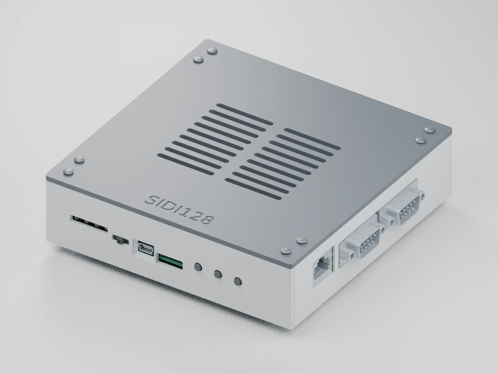 PRINTED / R18
PRINTED PARTS · HEAT-SET INSERTS
A compact printed base, four removable faceplates and a reinforced, vented lid. Two upper mounts on each faceplate secure the lid on all four sides.
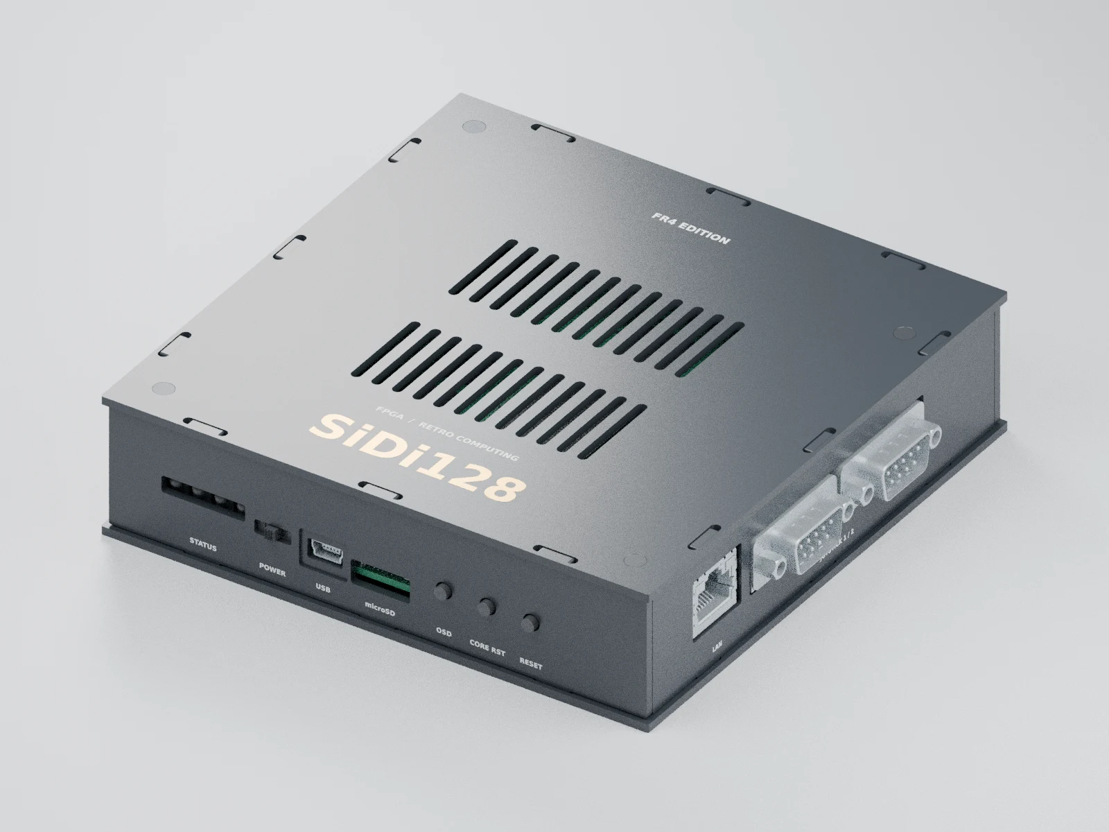 FR4 PANELS / R7
FR4 PANELS · METAL STANDOFFS
Six 2 mm FR4 panels meet at captured tabs. Two-piece metal post columns clamp the PCB, while separate countersunk screws secure the base and lid.
Both cases follow the revised board’s connectors, switches and microSD position. The 3D explorer shows the complete board inside each enclosure.
Three base mounting axes follow the VESA grid. Remove the lid for screw access, fit the monitor mounting hardware, then refit the lid.
Current CAD prototypes: printed R18 and FR4-R7. Dimensions exclude projecting connectors and external mounting spacers. Physical fit, thermal behaviour and mounting strength still need qualification. FR4 machining details are in the fabrication notes ↗.
06 / THE ASSEMBLY BOOK
Start with top assembly, then turn the board over and explore its stackup, routing and power guides.
Open the 5-page board guide ↗07 / WHERE WE ARE
The October 14 layout, with revised port positions and four fiducials. The board model matches the saved KiCad PCB on GitLab.
Native geometry throughout the interactive explorer.Printed and FR4 approaches, each with a vented lid, serviceable panels and mounting access through the open top.
Current models replace the earlier enclosure study.Physical assembly, connector access, firmware and core support, thermal checks and mounting validation.
Development models are separate from production qualification.